توضیحات
چکیده
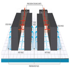
توپولوژی های معمول در مراکز داده شامل درخت های دو یا سه سطحی از سوییچها و روترها است. یک طرح سه سطحی شامل سطح (یا لایه) هسته در مرکز درخت، لایه توزیع 3در وسط آن و لایه لبه در برگ های درخت میباشد. یک طرح دوسطحی لایه توزیع را نداشته و تنها لایه هسته و لبه را دارد. یک چنین طرحی معمولاً 5تا 8هزار میزبان را میتواند پشتیبانی نماید. سوییچ های برگ درخت معمولاً تعداد قابل توجهی پورت GigEدارند (فرضاً 48تا 288عدد) و تعدادی پورت 10 GigEنیز برای اتصال به سوییچ های لایه بالاتر دارد. در واقع ترافیک میزبانها توسط لینک های 10 GigE به سوییچ های لایه بالاتر منتقل میشود. در لایه های بالاتر سوییچ هایی با تعدادی پورت ( 10 GigEمعمولاً 32تا 128پورت) و ظرفیت مناسب برای جابجایی ترافیک بین قسمت های مختلف لایه دسترسی وجود دارد. در یک مرکزداده فرضی این گونه توصیف شده است: در این مرکزداده ماشینها در رک1ها و ردیف هایی قرار میگیرند. این مرکز شامل 24ردیف و 12رک است. هر رک چهل ماشین دارد که توسط سوییچ Top of Rack (ToR) به هم متصل شده اند. این سوییچ یک پهنایباند دوطرفه non-blockingرا فراهم میآورد. سوییچ های ToRدر هر ردیف به یک سوییچ End of Rowمتصل میشوند. گاهی برای ایجاد قابلیت اطمینان هر سوییچ ToRبه چند سوییچ ( EoRمثلاً 4تا) متصل میشود. یک سوییچ EoRمعمولاً سوییچی 10 GigEاست که برخی پورت های آن به سوییچ های هسته متصل شده است.
معماری شبکه مراکز داده
ABSTRACT
Common topologies in data centers include two- or three-level trees of switches and routers. A three-level layout consists of the surface (or layer) of the kernel in the center of the tree, the distribution layer 3 in the middle, and the edge layer on the leaves of the tree. A two-tier design does not have a distribution layer and only has a core and an edge layer. Such a plan can usually support 5 to 8,000 hosts. Tree-leaf switches usually have a significant number of GigE ports (eg 48 to 288) and some 10 GigE ports for connecting to higher layer switches. In fact, host traffic is transmitted to higher layer switches by 10 GigE links. In the upper layers there are switches with a number of ports (10 GigE, usually 32 to 128 ports) and the appropriate capacity for moving traffic between different parts of the access layer. A hypothetical data center is described as follows: In this data center machines are placed in rows 1 and rows. The center consists of 24 rows and 12 racks. Each rack has forty machines connected by a Top of Rack (ToR) switch. This switch provides a non-blocking bidirectional bandwidth. ToR switches in each row are connected to an End of Row switch. Sometimes for each ToR switch, several switches (EoR, for example 4) are connected. An EoR switch is usually a 10 GigE switch with some ports attached to the core switch.
Year: ۲۰۱۶
Source : ۰
By : Ismail Amiri
File Information: persian Language/ 37 Page / size: 2.04 MB
سال : ۱۳۹۵
منبع : ۰
کاری از : اسماعیل امیری
اطلاعات فایل : زبان فارسی / 37 صفحه / حجم : MB 2.04


نقد و بررسیها
هنوز بررسیای ثبت نشده است.