توضیحات
چکیده
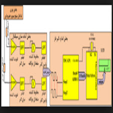
در اين مقاله ساختار جديدي براي نوسان ساز متعامد با مدار تشدید LCو فركانس كنترل شونده با ولتاژ، قابل پياده سازي در فناوري CMOSارائه مي شود. در مدار پيشنهادی ، دو نوسان ساز اتصال ضربدري LCيكسان از طریق زیر لایه هاي (بالك) ترانزيستورهاي اتصال ضربدري و ترانزيستورهايي كه نقش خازن متغير را دارند، به يكديگر تزويج شده اند. در اين مدار نيازي به هیچ قطعه اضافي براي تزويج دو نوسان ساز هسته نيست و در نتيجه هيچ منبع نويز و توان مصرفي به مدار اضافه نميشود كه باعث بهبود نويز فاز و كاهش توان مصرفي در مقايسه با مدارهاي مشابه قبلي ميگردد. اين مدار كارقابليت با ولتاژ تغذيه به كوچكي 5/0ولت را دارا ميباشد. يك تحليل خطي براي نشان دادن متعامد بودن خروجيهاي مدار پيشنهادي ارائه ميشود .این روش تزويج ميتواند براي توليد سيگنالهاي چندفازه نيز بكار گرفته شود.
مقدمه
امروزه نوسان سازهاي متعامد به طور گسترده اي در مخابرات بيسيم و باسيم در فرستنده-گيرنده ها و مدارهاي (Clock and Data Recovery) بازيابي كلاك و داده بكارگرفته مي شوند .تقريبا همه ساختارهاي مبتني بر سيگنالهاي متعامد براي انجام مدولاسيون، دمدولاسيون و حذف تصوير نياز به نوسان سازهاي متعامد دارند . روش های چندي براي توليد سيگنالهاي متعامد وجود دارد .در يك روش از اختلاف فاز دو مدار خازن- مقاومت (RC-CR) برای ایجاد دو خروجي متعامد استفاده ميشود. نقطه ضعف اين روش، نياز به بافرهايي با توان مصرفي بالا، و دقت فاز كم آن ناشي از بالا در خطاي مقاومت اندازه بر روي تراشه مي باشد و در روشي ديگر از يك نوسان ساز با فركانس دو برابر فركانس دلخواه و یک فليپ_ فلاپ به عنوان مقسم فركانس استفاده ميشود اما ضعف اين روش، محدوديت فركانس كار و زي ن حساسيت شديد خطاي كار به چرخه آن فاز نوسان ساز ورودي ميباشد . یك روش یک روش دیگر برای توليد سيگنال های متعامد بكارگيری نوسان سازهاي حلقوي است، اما با وجود داشتن بازه تنظيم فركانس گسترده، به علت نويز فاز آنهاي بالا در مدارهاي مخابراتي به كار گرفته نمي شوند.
ABSTRACT
In this paper, a new structure for an orthogonal oscillator with a LC amplification circuit and a voltage controlled frequency can be implemented in CMOS technology. In the proposed circuit, two LC transverse oscillators are equally coupled through the underlying layers of the transverse transistors and transistors that have a variable capacitor role. In this circuit, there is no need to add any additional components to the coupling of the two oscillators, and as a result, no noise source and power consumption are added to the circuit, which improves phase noise and reduces power consumption compared to previous circuits. This power supply circuit with a voltage of 0.5 V is small. A linear analysis is presented to illustrate the orthogonality of the proposed circuit outputs. This coupling method can also be used to generate multiphase signals.
INTRODUCTION
Today, orthogonal oscillators are widely used in wireless and wireless communications in clock and data retrieval systems. Almost all orthogonal signal structures are used to modulate, demode, and remove image requirements. They have orthogonal oscillators. There are several methods for producing orthogonal signals. In one method, the phase difference of the two capacitor-resistance circuitry (RC-CR) is used to create two orthogonal outputs. The disadvantage of this method is the need for high-power buffers, and the low phase accuracy is due to the high resistance error on the chip, and in another method, an oscillator with a frequency of twice the desired frequency and a flip-flop as Frequency frequency is used, but the weakness of this method is the frequency limitation of the work and the high sensitivity of the work error to the cycle of that phase of the oscillator. One method is another way of producing orthogonal signals for the use of circular oscillators, but they are not used in telecommunication circuits, despite having a wide frequency range, due to their high phase noise.
Year: 2010
Publisher : Eighteenth International Energy Conference of Iran
By : Imad Ebrahimi, Sasan Naseh
File Information: persian Language/ 6 Page / size: 558 KB
سال :1389
ناشر : هجدهمین کنفرانس بین المللی برق ایران
کاری از : عماد ابراهيمي ,ساسان ناصح
اطلاعات فایل : زبان فارسی / 6 صفحه / حجم : KB 558


نقد و بررسیها
هنوز بررسیای ثبت نشده است.